|
NINGBO CRRCTIMES TRANSDUCER TECHNOLOGY CO.,LTD.
|
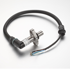
Rotation Speed Sensor
| Payment Terms: | T/T,T/T |
| Place of Origin: | Zhejiang, China (Mainland) |
|
|
|
| Add to My Favorites | |
| HiSupplier Escrow |
Product Detail
Operating temperature: -25℃~+100℃
Speed measuring range:1000rpm~33000rpm
Signaling hole: 2×Φ4, depth 3 mm
TBT1C Rotation Speed Sensor
Application
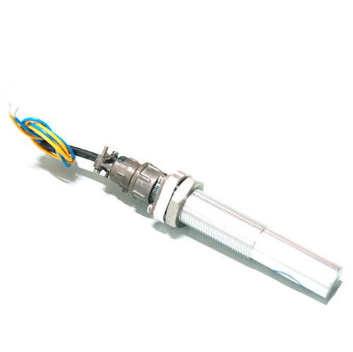
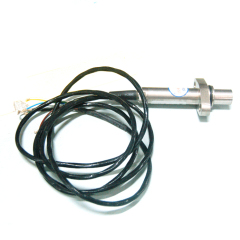
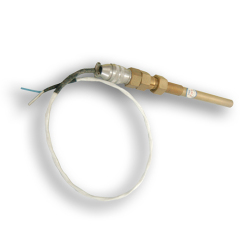
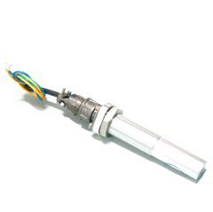
TBT1C rotation speed sensor is a magnetoelectric rotation speed sensor, and it is installed to
the case or case cover of transmission gear, the tested rotary object is magnetic steel. It is
composed of electrical inductance coil, shell, shield cable, connector, etc. Output signal is similar
to sine wave, adapting operation with other speed measuring control equipment in the various
transport facilities. The sensor can detect the rotational speed of transmission gear and the speed
of transport, applicable to various transport facilities.
Features
Wide temperature accommodation
Wide speed measuring range
Strong shock resistance
Good tightness
Non-contact with tested gear, without abrasion
onvenient installation, simple and reliable
Main Technical data
Operating temperature: -25℃~+100℃
Speed measuring range:1000rpm~30000rpm
Tested object:Magnetic steel
Signaling hole: 2×Φ4, depth 3 mm
Operating air gap: 100mm X 100mm
Output waveform: Similar to sine wave
Output channel: 1
Coil resistance: 1.3K?±10%
Output feature: 1000rpm & Load resistance 10K? Vp-p≥0.1V
Insulation resistance: ≥200M?(500V Megohmmeter)
Insulation strength: 500V/50Hz/1s
Output short-circuit protection: Available
2 2
Vibration and shock: Vibration 5.9 m/s ;Shock 30 m/s
Interface: X14J4A /X14K4P
The definition of cable & connector output function 
Installation\operation and malfunction disposal Forbidden contact between terminals; otherwise the permanent-magnet would be
demagnetized greatly, even damaged. Output wire distribution as per the definition strictly, and ensure it correct, without short
and open circuit; After installation of sensor, tighten locknut; When check the sensor, use the multimeter to measure DC resistance (connector pin1
and pin 3 or pin 2 and pin 4), the resistance should comply to 1.3K?±10%, which shows the
sensor work normally.
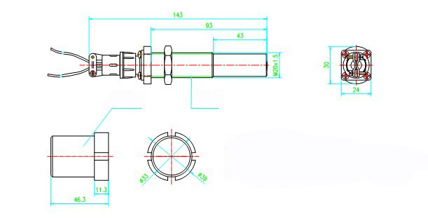
Outline and installation drawing 